
The Theory of X-Ray Diffraction
Diffraction occurs when incident X-rays constructively interfere with a crystalline solid such that Bragg’s law is satisfied.

When x-rays reflect off a set of planes in a crystalline structure, constructive interference occurs when the path difference (Δ) between the x-rays is equal to their wave length (λ). The path difference is controlled by the distance between the planes (d) and the angle at which the x-rays hit the set of planes (θ, 2θ). If the angle is such that Bragg’s Law is not satisfied (Δ ≠ nλ) then deconstructive interference occurs.
Crystalline solids have several sets of lattice planes within their crystal structures. If you powder a sample so all the particulates are randomly orientated and scan through a range of 2θ, you can find the case where Bragg’s Law is satisfied for all the sets of planes in a solid (A).
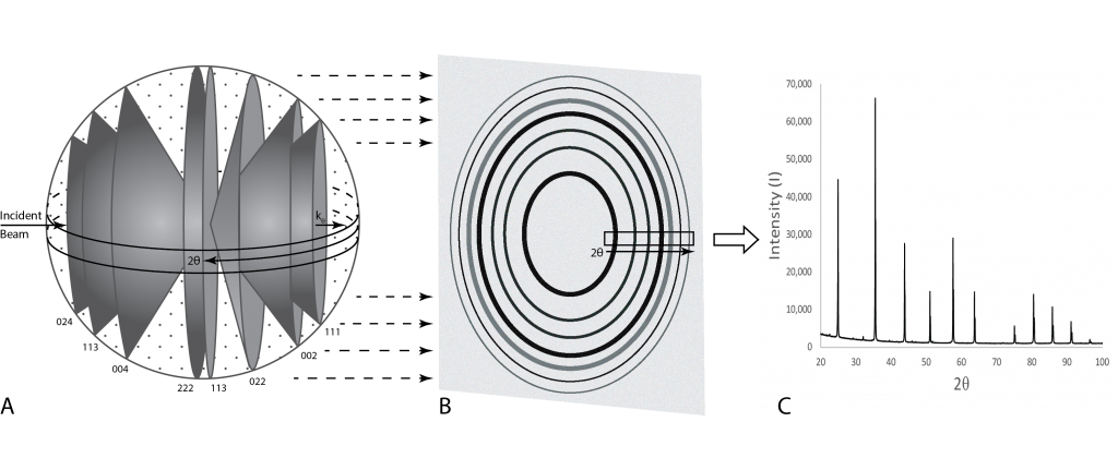
To detect these x-rays photographic film was used in the past. Each case of constructive interference would produce a ring, the position of which would relate to the 2θ angle where it occurred. The darkening of the rings indicated more x-rays being reflected, which is related to the elements present in that set of planes (B). Now we use detectors that scan through a range of 2θ to determine the peak positions where interference is occurring (2θ) and the number of x-rays detected (I) which then is then plotted on a graph (C).
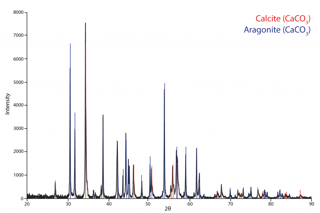
Each crystalline solid will have a different structure, set of d-spacings, and intensities creating a unique “fingerprint”. The International Centre of Diffraction Data (ICDD) has an extensive library of known diffraction patterns for a wide range of materials which can be used to search/match to identify a detected phase or phases in an unknown sample (see example below). Phase identification is the main application of XRD.
XRD can also be used for more advanced applications such as determining the structure of new substances, determining the crystallinity of a substance, or to do semi-quantitative estimations of the abundances of phases within a multi-phase sample (See Applications Page for details).
For a more detailed video explaining X-Ray Diffraction please click the following link.
The X-Ray Diffractometer
An X-Ray Diffractometer is the instrument we use to produce monochromatic x-rays, focus the beam on a sample, scan through a range of 2θ, and then detect the reflected x-rays and their intensity.
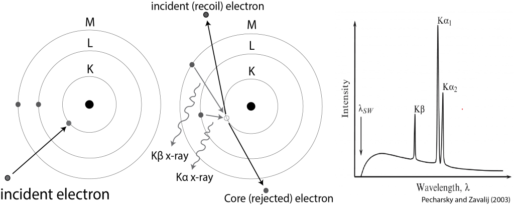
Monochromatic x-rays are generated in a cathode ray tube. A filament of tungsten is heated to produce electrons which are then accelerated towards an anode material (i.e. Cu, Co, Mo, etc.). On impact electrons are dislodged from the inner shell and when electrons from higher shells fall down to take their place, an x-ray characteristic of the anode material is released. (See figure below).
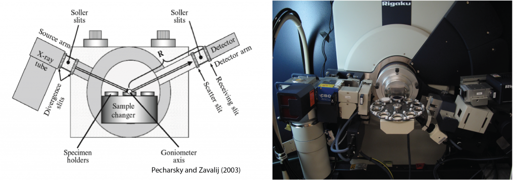
The x-ray tube and detector are attached to a goniometer that rotates the arms synchronously to scan through a programmed 2θ range. A set of optics focus the x-ray beam on the sample which then reflect up into the detector which is positioned at the same angle opposite to the tube (See figure below). When constructive interference occurs, the detector records the peak position and intensity which is the then displayed on a diffractogram.
References:
Pecharsky, V. K., & Zavalij, P. Y. (2003). Fundamentals of powder diffraction and structural characterization of materials. Boston: Kluwer Academic Publishers.